
switches
This week has been about creating symbols in KiCAD for each relevant chip we’ll be using on little cloud’s circuit board. Turns out it’s hard to find well-organized ready-made symbols for the Chinese parts we’ve selected due to cost-effectiveness. Though nowadays we can learn about these parts from their Chinese datasheets using LLMs, so it’s pretty doable. While I did the schematic symbols, the packaging formats are pretty standard and so KiCAD does have most relevant footprints and 3D models baked into the standard library, such as MSOP-10 or QSOP-24 for the USB switches we’ll be using for host workers (see previous update).
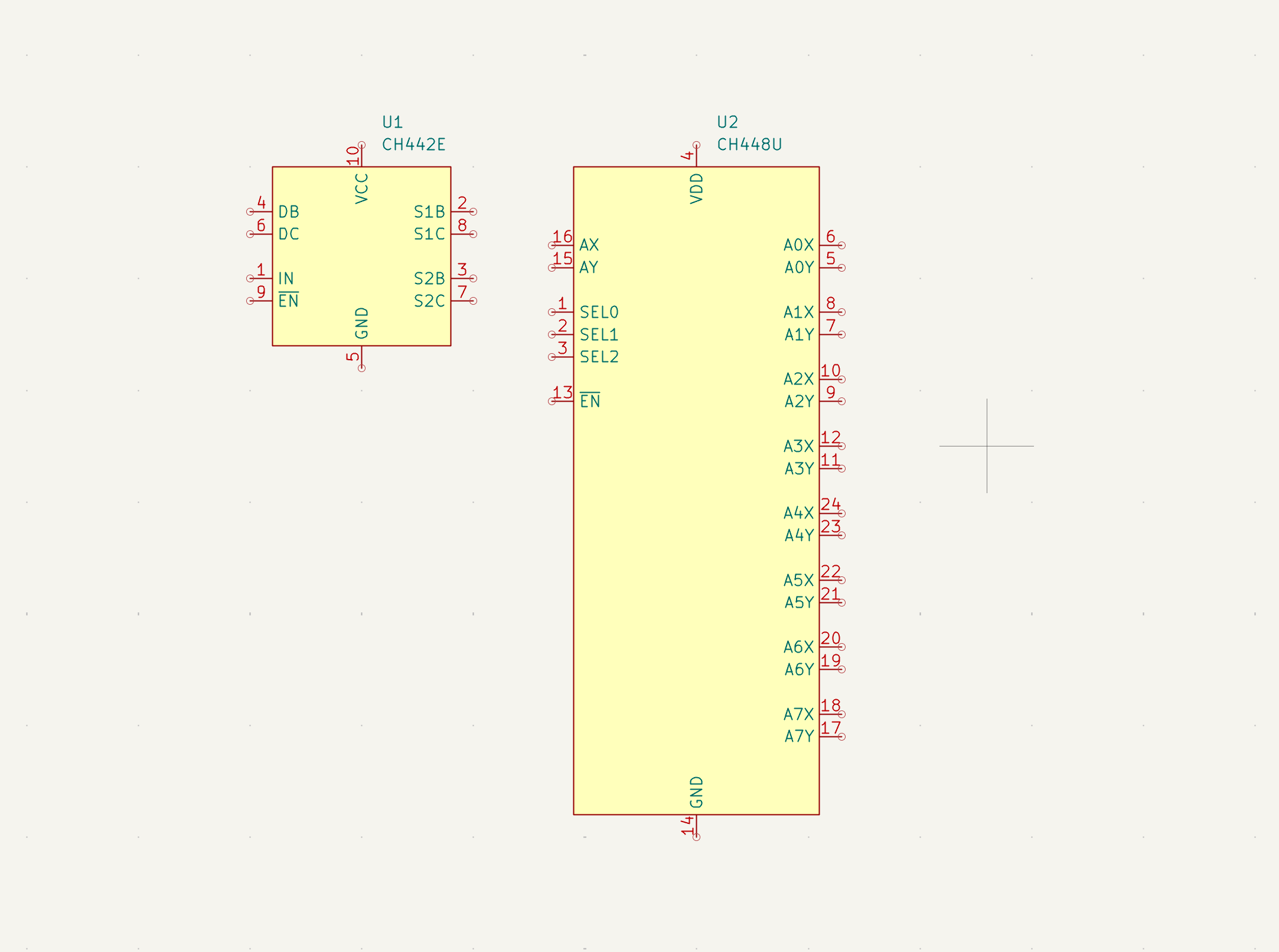
I was dreading the mechanical task of annotating, for instance, 24 pins on the CH448U switch, but it turned out to give me a proper chance to get familiar with the parts I’ll be using, which I don’t regret. Some gotchas to be aware of are active-low pins and bit ordering for the selector.
By the way, the reason I’m looking at both the CH442E 2:1 switch and the CH448U 8:1 switch ($0.1@1K) is because of the following. If we only did 2:1 switching to toggle a port to use the microprocessor’s (MPU) USB device bus, we’d end up with an unterminated stub going to the switch of each port that doesn’t connect to that. At USB high-speed frequencies, physics would complain through reflections and capacitance. Instead, we also place one 8:1 switch on the device bus to “confirm” the port connecting to it and ensure the connection there remains cleanly point-to-point.
eth
Moving on to the Ethernet specific parts, they were a bit weirder. The fact that they mix different high-speed protocols that they need to partially process in silicon makes them require odd power routing. For instance, the the USB-to-Ethernet RTL8152B nominally only requires a +5V power input into the chip. However, it also produces other specific voltages on other pins, as power outputs. But this isn’t a convertor or anything, these power outputs shouldn’t be used by other chips. But then, why route them out to the chip’s pins, you might wonder. Well, because we need to do some filtering and decoupling outside the package, to protect the sensitive internal circuitry from the noise as much as possible, and then route that back in on a different pin. Kinda weird.
Also, because our MPU only exposes an Ethernet MAC interface, while previous $0.8@1K choice of Ethernet switch only exposes PHY interfaces, we need to upgrade to a switch that also exposes at least one MAC one. It turns out that if you want at least 5x PHYs (for connecting to the USB-to-Ethernet chips) and 1x MAC on the switch, then the cheapest version that supports Gigabit speeds costs the same as the one that supports 100 Mbps only, at ~$1.5@1K. Maybe the 100 Mbps part is scarcer or something. Anyway, it means we effectively get a 10x upgrade on the interconnect between MPU and Ethernet switch, because it costs the same. The downstream port connections are still capped at 100 Mbps, but the MPU-switch link was more of a bottleneck. Any USB host and device workers would cross that link to communicate.
Or would they? Here’s an idea of how to increase the bandwidth between workers at no additional hardware cost. We already said we might use a worker device’s WiFi radio to connect to the internet. Well, we can also get them to connect to each other with low latency as an add-on to the wired connection that also handles charging and recruitment. This can double or triple the aggregate throughput between them, a feature especially relevant for inference workloads with bits of the LLM split on different workers.
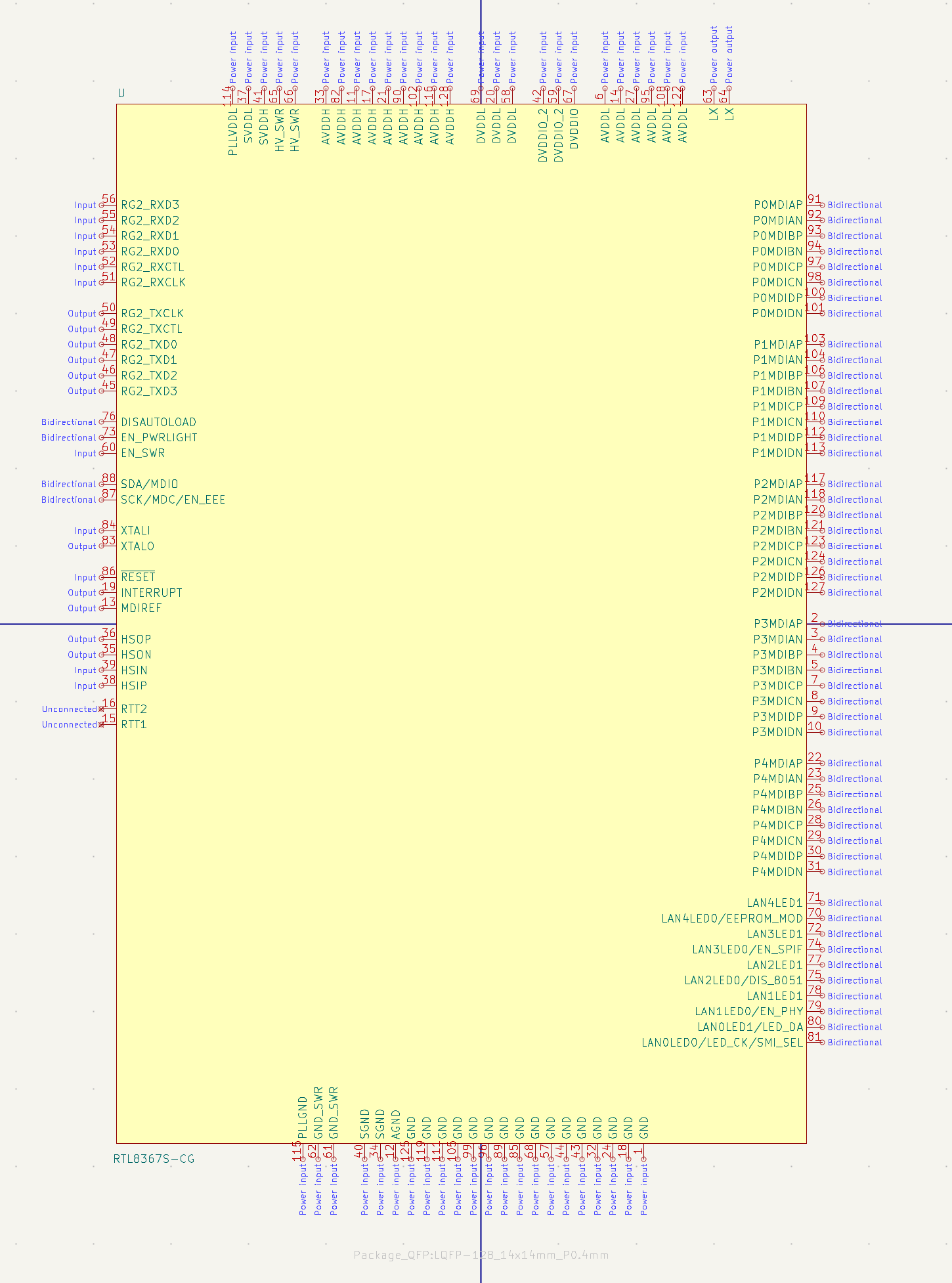
The switch symbol itself was quite a beast compared to the previous ones, at around 128 pins. A third or so of which were power related, I guess this is the actual status quo with mixed-signal chips. The Gigabit MAC interface will hook into the MPU’s, and the Gigabit PHYs on the right will hook into the USB-to-Ethernet chips, though only half the channels because the latter are 100 Mbps only. I didn’t expect a 1.5$ fixed-function chip like this to have so many bells and whistles, an integrated microcontroller which we won’t touch, options to attach separate configuration memory which we won’t use, etc.
usb
Then came the USB power delivery controller we’ll be using to negotiate with an upstream charger to get the power we need for smartphones and tablets. Quite tiny compared to the 128-pin switch, but packed with features. It can be set to default to a 5V contract in order to power the MPU, which then comes back and asks it to negotiate more via I2C. It also has support for legacy fast-charging protocols, to be able to talk with chargers that predate USB PD. Why not.
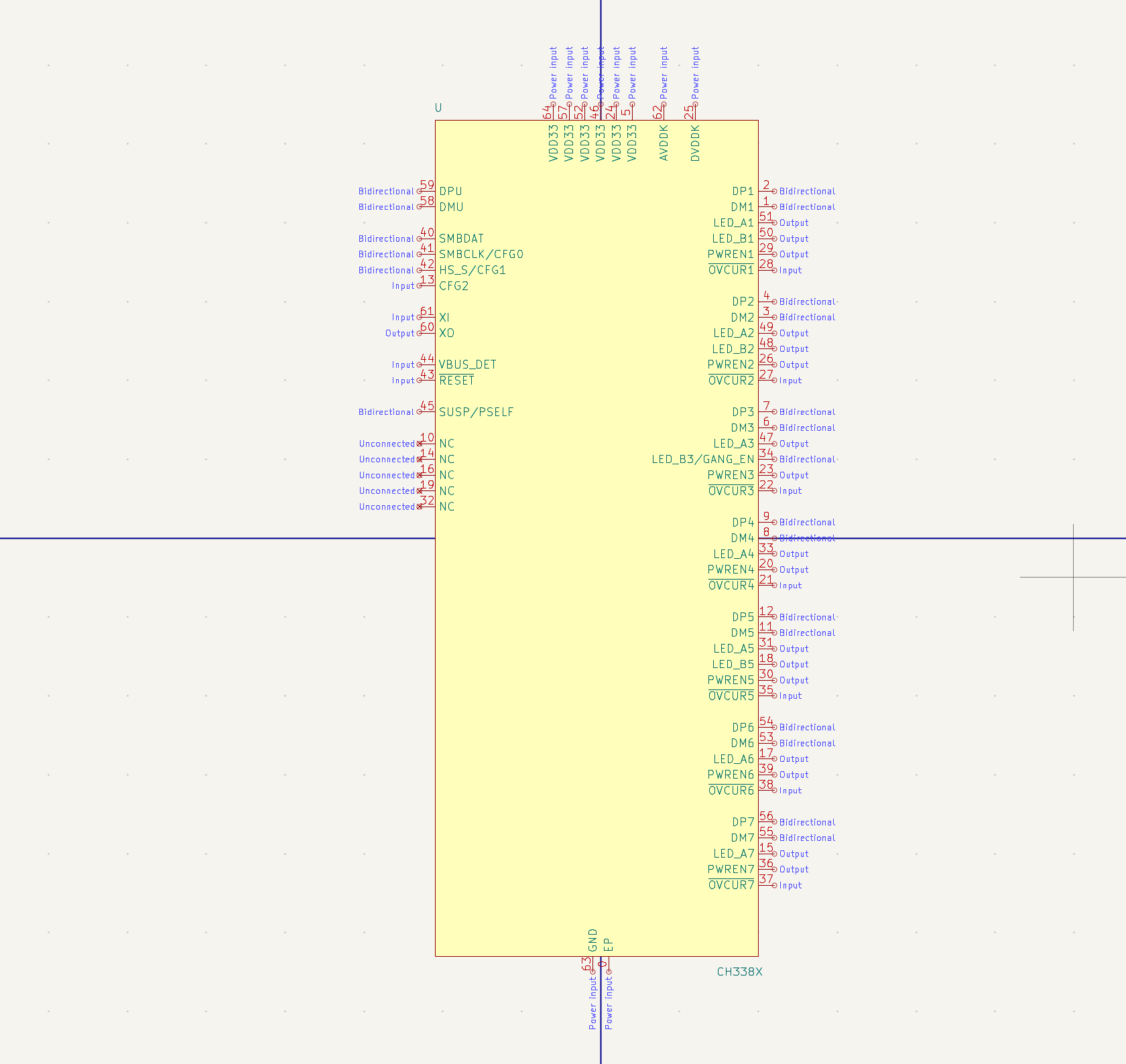
The 7:1 USB hub resembles the earlier 8:1 analog switch that can work with USB signals. It has some more LEDs, supports configuration memory which we won’t use, and has a few other bells and whistles. Still very manageable compared to the 128-pin switch and upcoming MPU.
mpu
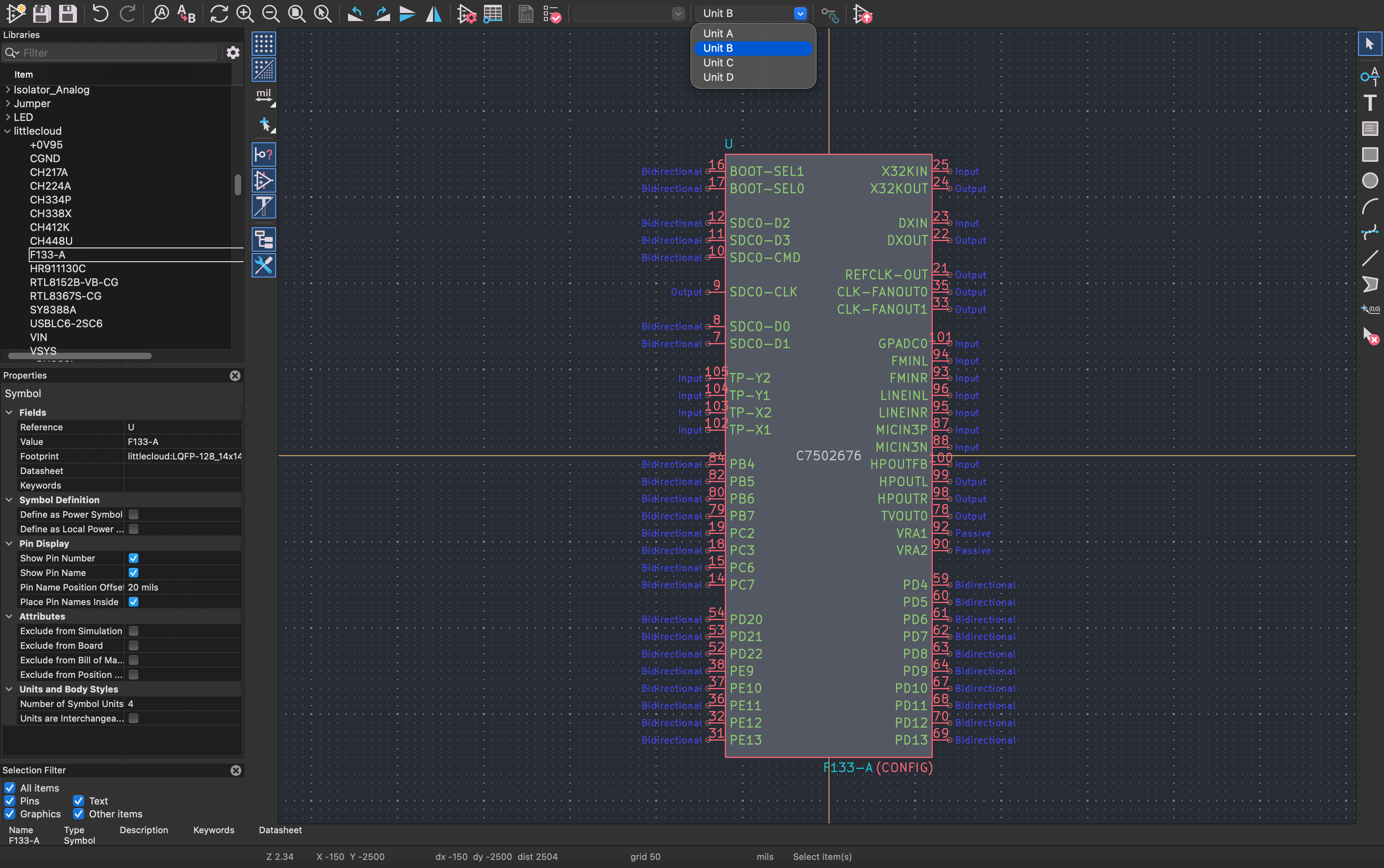
Then came the centerpiece, the Allwinner MPU. It doesn’t have more pins than the Ethernet switch, but they’re more diverse. I had to also add in an exposed pad in the footprint, because the KiCAD library lacked such a variant. Apparently different manufacturers size the exposed pad differently, so maybe that’s the reason. Anyway, the MPU has it all, a bunch of really handy interfaces you can toggle the pins to inherit programmatically. Half the work on this symbol was pruning away the functionality such that we only get the features we need instead of half a dozen options per pin listed in the label. Ran my symbol and the datasheet through LLMs to spot typos and mismatches, which there were quite a few of. Hopefully the symbols are stable enough to use conveniently in the schematic.
non-technical
Been also looking into ways of minimizing little cloud’s price beyond the physical parts that go into it, namely in terms of legal and logistics. From further research into relevant regulations for selling across the EU, we’ll need to align with the Electromagnetic Compatibility Directive (EMC) for Electromagnetic Interference (EMI) and Electrostatic Discharge (ESD) concerns. We’ll need to align with Restrictions of Hazardous Substances (RoHS) for self-evident reasons. General Product Safety Regulations, too. Thing is, for our Energy Source 1 (<75V DC) and Power Source 2 (<100W) class, and in a consumer setting, it tentatively seems like we can achieve compliance by simply ensuring the design adheres to standards, documenting it, testing it internally, and then just self-declaring the results. No authorized lab or notified body with eye-watering quotes, seemingly.
But there’s a thornier compliance issue: WEEE, or e-waste management. Thing is, little cloud might reduce e-waste by helping households breathe new life into old electronics. But, it would itself be an electronic product, that can only be sold to consumers in the EU through settings that involve registration with local institutions responsible for e-waste. Annoyingly, these are not really harmonized or integrated beyond the national level, making it such that you require a legal entity in each member state where you want to sell directly.
Now, the catch is that if you sell to businesses in other member states, such as local distributors of maker products, they take on the responsibility for local WEEE concerns. They’re properly registered as a seller of electronics, etc. They also handle returns, replacements, and buffer local storage for cheaper and faster deliveries. Of course, they also take their cut. But you could sell to multiple distributors in the same region to drive lower markups on that leg of the product’s trip. Let’s say the marginal cost of a little cloud at 1K volume is 30€, it might be possible to barely get it on various EU shelves at around 40€, before VAT and shipping. Not great, not terrible.
There’s also another approach I found, namely that of “co-creation” with a “design partner.” Basically, you bring the idea and a working design, and they take it on and manufacture, sell, and ship it. They give you a royalty fee for the IP. Now, sure you might get the best margins if you sold directly or through distributors. But then, this is not what we’re here for. Co-creation could potentially be interesting in that it lowers the underlying cost of goods quite a lot, because the design partner has huge quantities of relevant parts already. Some programs like this focus on integrating new modules in an ecosystem, which isn’t too interesting here. But if I find a program where they handle the logistics and put pressure on the final price, I might be down for that.