stages
Let’s recap the quest for a satisfactory approach to little cloud’s hardware. Early on, my best guess was that we’d go with some very specific microcontrollers manufactured by WCH, using them to flexibly drive USB ports. But that felt complex and overfit to WCH’s offering. Over the past couple weeks, my best guess was that we’d fold everything we need into an FPGA as soft cores, including a processor, USB buses, and so on. But that irresistible appeal of total consolidation quickly died with a reality check of trying to synthesize all that on a budget FPGA. So where do we go next?
Here’s my intuition after a few weeks of turning this problem over on a bunch of sides. The promise of USB lies in its universality. It can enable a flash drive holding an OS, it can support networking between devices, it can be used to control smartphones, and so on. But perhaps we jumped to the wrong conclusion when we mandated that every single port needs to be able to do everything at anytime.
The following nuance is growing on me. Recruiting devices is much messier than orchestrating them, but only happens occasionally. You talk differently via USB to a smartphone than to a desktop to recruit them as worker devices into a cluster. But orchestration could be made to only require a reliable network once the worker has been recruited.
split
Because recruitment generally only happens once per device, and only one device is being recruited at a given time, the whole recruitment hardware can boil down to a single dual-role port or two single-role ports. Want to recruit an Android smartphone or tablet? Have little cloud present itself as the host and drive it via ADB. Want to recruit a laptop, desktop, or server? Have little cloud present itself as a composite of a mass storage device holding a minimal OS and a HID keyboard device to handle the boot or install. At the end, just make sure you’ve left a privileged shell for little cloud to reach.
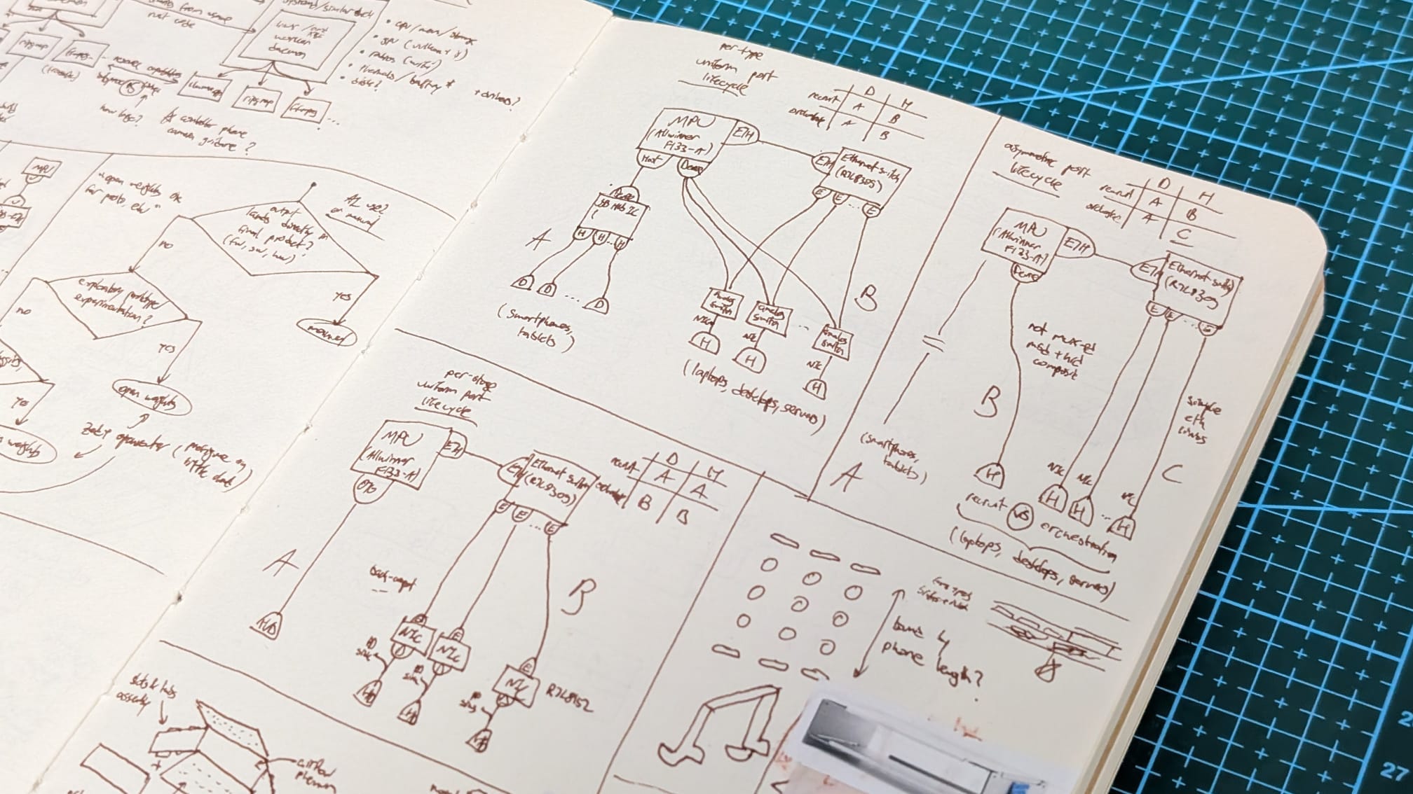
Because orchestration is constant but generally only requires reliable networking, the orchestration hardware can boil down to making sure there are many network-capable ports, either device-only or per-type. The device-only option is to only use fixed-function USB-to-Ethernet chips (~0.6$ @ 1K), and connect them all plus the microprocessor to one switch (~2$ @ 1K). The downside here is that smartphones and tablets lacking dual-role power (manufactured prior to ~2017) wouldn’t be able to be charged on the same cable. This is because these chips present themselves as USB devices, and only on Type-C with full power delivery (PD) support can the two sides swap power roles.
The other orchestration option would be to have one USB host bus combined with a standard hub chip for smartphones and tablets, and the Ethernet switch for laptops, desktops, and servers. More backwards-compatible, but less uniform. Yet what I like about this option is that it lacks microcontrollers and FPGAs entirely. Just a microprocessor and a few fixed-function chips that just need to be placed properly. One firmware only, and no gateware.
block
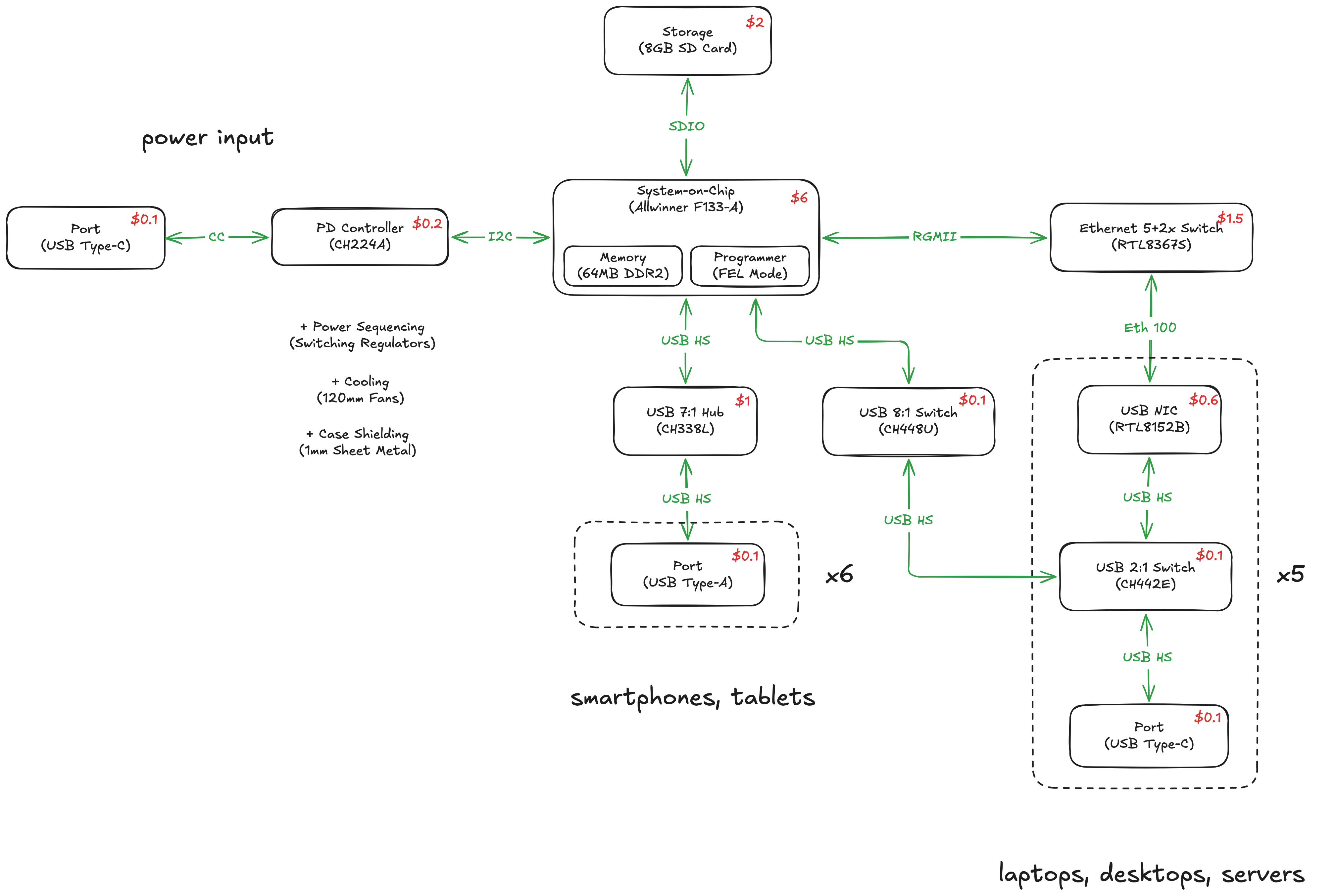
So I got the Advanced Digital Hardware Design course from Phil’s Lab that I mentioned in a recent update, primarily to use as an outline when working on little cloud’s board. The first thing to follow along with was a high-level block diagram of the system architecture, so I made a slightly cleaner version that draws from various rough sketches from my notebook, with part numbers, costs at 1K, used interfaces, etc. It reflects this third approach described in the previous sections, where we split hosts and devices, and use neat fixed-function chips on the host side to cheaply aggregate them.
I notice that while the “data plane” is pretty well-specified, I’m still somewhat confused as to how to approach power. We’ll get to that while following along a lesson focused on this, but I can already see there’ll be a few different subsystems related to it. We’ll need to negotiate a variable USB PD profile from upstream and convert that to 5V efficiently, we’ll need a way to power sequence the System-on-Chip and give it a few different voltage rails, and we’ll need to power the USB devices in a way that preserves battery life and minimizes heat. We’ll get there eventually.
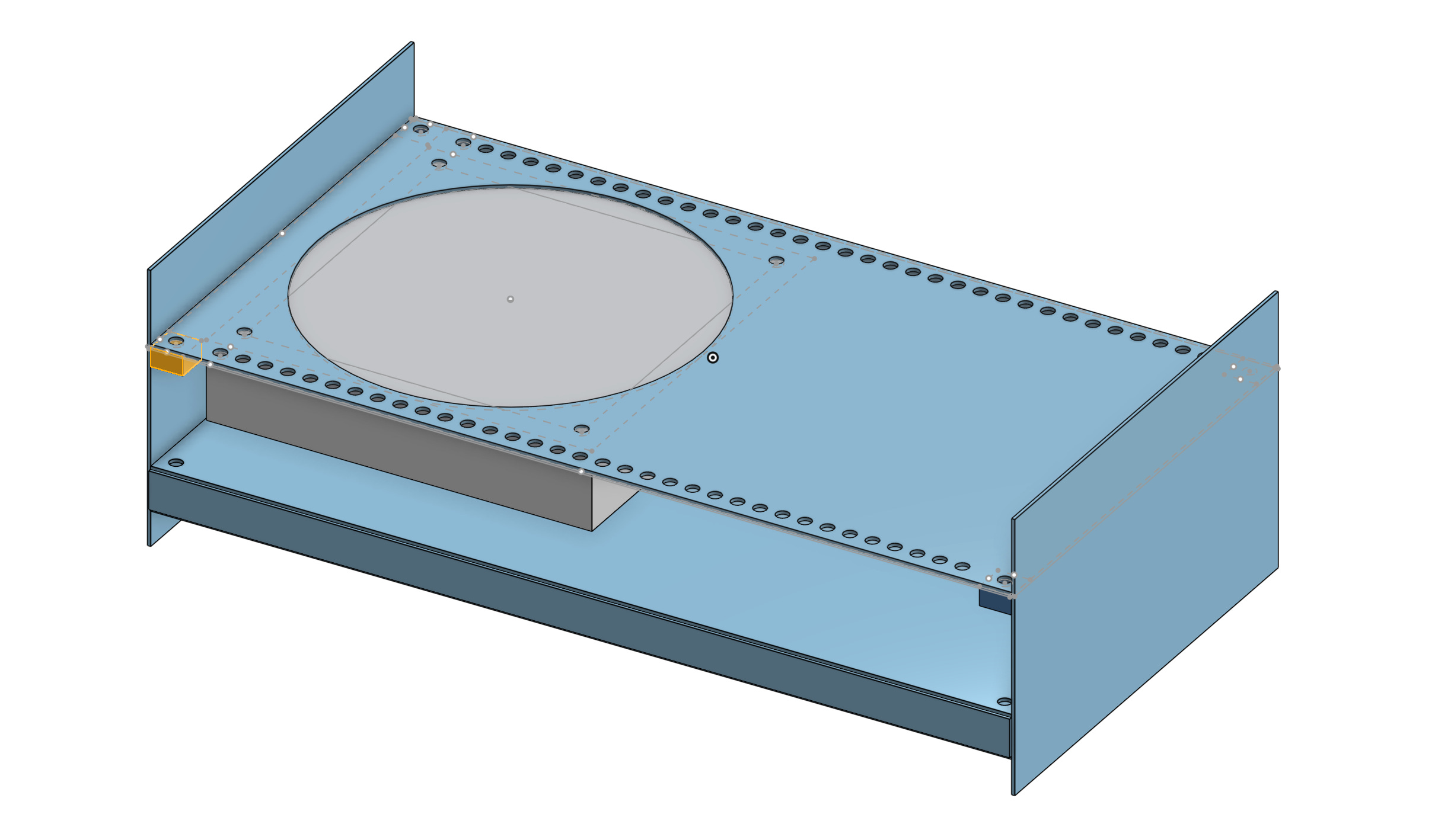
Also, I realized that our dozen or so different USB high-speed and Ethernet 100mbps connections might be a source of electromagnetic interference (EMI) issues, which gets tested during product safety certifications. We’ll really need to nail grounding and shielding and filtering, and so I’ll probably walk back on the standoff sandwich approach to the enclosure and go with a fully enclosed one instead, see update #5. And I might fold the fan grills back into the enclosure, although with a simpler layout, to ensure we can ground the 120mm fan holes, too.
maximalist
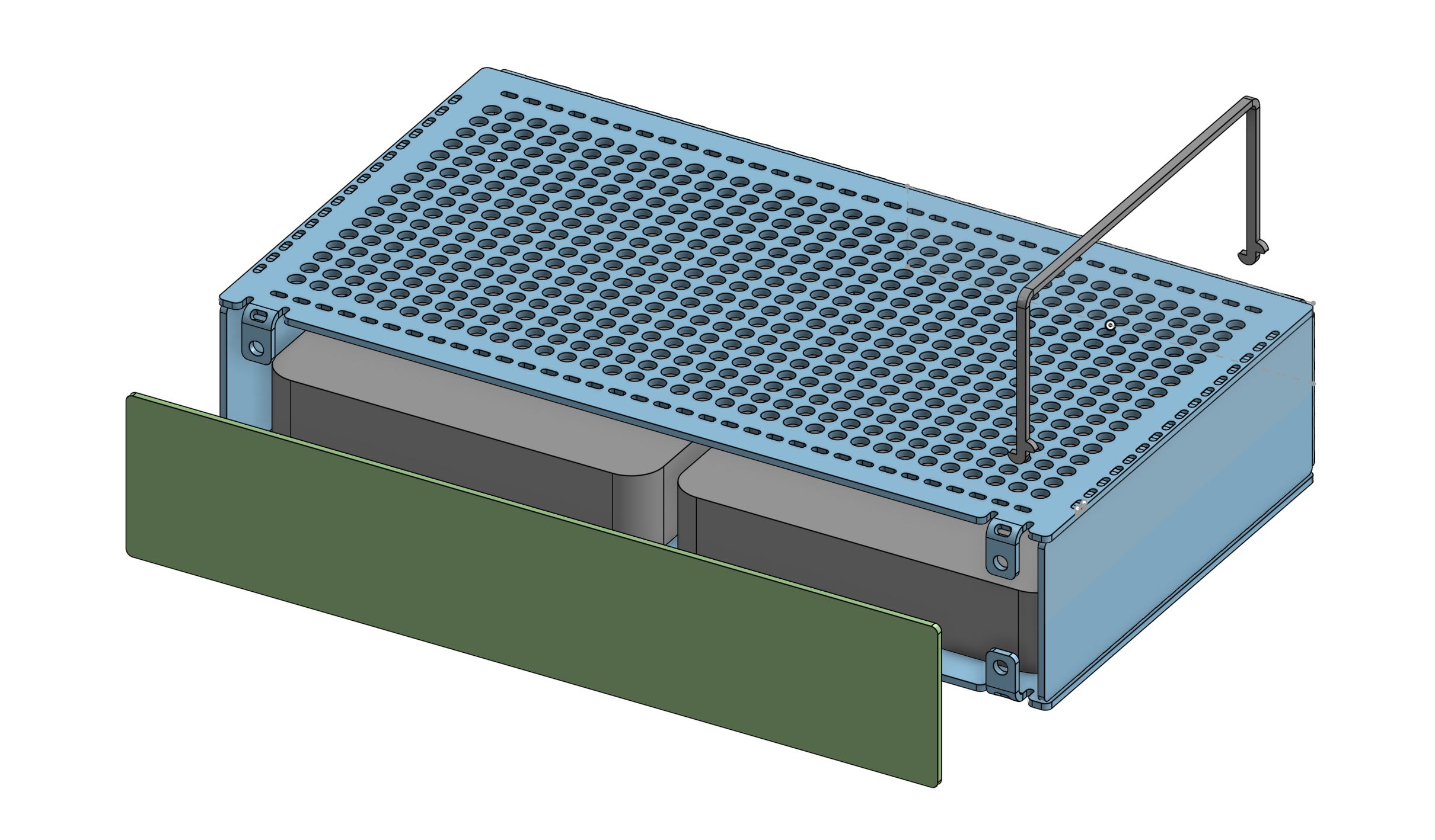
I did another iteration on the enclosure, feeling a bit paranoid about the product safety certifications we’ll need to nail early to avoid extra spins. There’s the EMI aspect, where we essentially want to shield the high-frequency circuitry with the enclosure as much as possible, ideally with no large openings. Then, there’s the fire safety stuff, which to really make sure we cross it, we’d again ideally enclose “potential ignition sources” inside metal. Our enclosure here is also critical for airflow, so maybe we could have a plenum to distribute it uniformly across devices? Though not sure how important the latter is.
The result of optimizing for comfortably passing certifications in this iteration led to a somewhat overengineered design. The PCB ended up the front panel, but with all surface-mounted components on the inside face. The airflow grills resemble the original (expensive and dense) hole matrix design due to seeking EMI shielding. The sides have matching tabs and slots to aid assembly, which is the first time I tried something like this. Critical flaw: the ports facing upwards would be obstructed by the worker devices occasionally.
Similar to how we’ve relaxed constraints on the hardware schematic side of things over time, I think the enclosure could also get the same treatment. With this overengineered design in mind, I’m thinking we could handle PCB enveloping (for EMI and safety), separately from airflow to worker devices. And so maybe we could use simple wire mesh grills for fan outlets, as well as plates on standoffs, even if not ideal for EMI. And that because we could separately sandwich the PCB tightly between sheet metal plates in its own area, outside the airflow path entirely. The search continues.
cubes
Here’s another iteration, following the idea of decoupling the PCB shielding from airflow paths. We basically structure the solution around a few different floors. Worker devices sit on the roof. On the floor below, we have a chamber dedicated to ventilation, as well as power brick storage. The back side is missing, to allow air intake and access to storage. On the floor below, we have the actual PCB, enclosed on all sides. A tiny panel turned off in the render would be placed flush against the ports. Also, the sides in this flat-only iteration can extend upwards to create handles and downwards to create feet to avoid resting on tiny screws and scratching the table or below.
I also tried incorporating these neat fasteners, called threaded cubes. They’re basically female-female standoffs but 3D instead of 1D. They’re pretty handy for interlocking flat plates on multiple sides without countless flanges. Even compared to 2D 90° brackets, these allow us to use fewer parts, as some of them connect on even 4x sides. They come in cute colors and are dirt cheap in volume, maybe it’s a way to add an accent color to an otherwise spartan choice of parts.
Of course, once actually modeling it based on some rough sketches, I realized we could potentially make some improvements. If we limit one side of the PCB to at most low-speed signals like LEDs, like in the previous sections, we could skip the metal sheet that currently separates the two internal floors, as well as 4x threaded cubes. One of the PCB plates becomes the metal sheet roughly, but with the ports oriented correctly this time, and with a better structure around it. However, the laptop power bricks that might reasonably be placed in the storage areas might need to be isolated themselves from the PCB, as they have mains AC inside, transformers and switching, and so maybe the extra sheet isn’t too bad for different reasons.